思科常用命令
show指令不能在全局配置模式下使用
| 命令 | 功能 |
|---|---|
| show interface | 查看所有端口的信息 |
| show vlan | 查看所有VLAN的信息 |
| show vlan brief | 查看所有VLAN的简要信息 |
| show interface interface-id switchport | 查看指定端口的接入模式 |
| show mac-address-table | 查看MAC地址表的内容 |
| show ip protocols | 查看路由协议相关信息 |
| show startup-config | 查看系统配置 |
| show running-config | 查看当前的运行配置 |
| copy running-config startup-config | 更新系统配置 |
| write | 保存配置 |
| reload | 重启交换机 |
| enable | 进入特权模式 |
| disable | 退出特权模式 |
| exit | 退出到上一级配置模式 |
| end | 退出到特权模式 |
| hostname newname | 设置交换机名称(需要先进入全局配置模式) |
| shutdown | 禁用端口 |
| no shutdown | 启用端口 |
| configure terminal | 进入全局配置模式 |
| vlan vlan-id | 进入VLAN的配置界面 |
| name vlan-name | 设置VLAN名称(需要先进入VLAN配置界面) |
| no vlan vlan-id | 删除指定VLAN |
| interface vlan vlan-id | 进入指定VLAN的配置模式(VLAN其实就相当于一个虚拟端口) |
| interface interface-id | 进入指定端口的配置模式 |
| interface range interface-id | 进入批量配置端口的模式 |
| duplex full | 设置端口为全双工模式(需要先进入指定端口配置模式) |
| speed xxx | 设置端口的速度(需要先进入指定端口配置模式) |
| ip address ip-address subnet-mask | 设置端口的IP地址和子网掩码(需要先进入指定端口配置模式) |
| switchport mode access | 设置端口为VLAN接入模式(需要先进入指定端口配置模式) |
| switchport mode trunk | 设置端口为中继模式(需要先进入指定端口配置模式) |
| switchport access vlan vlan-id | 将指定VLAN分配给某个端口(需要先进入指定端口配置模式) |
开启telnet
shell
Switch>
Switch>enable
Switch#configure terminal
Enter configuration commands, one per line.  End with CNTL/Z.
Switch(config)#interface vlan 1              // 进入vlan 1的配置模式
Switch(config-if)#ip address 192.168.0.254 255.255.255.0     // 设置telnet地址,用来远程登录
Switch(config-if)#no shutdown                // 让配置立即生效
Switch(config-if)#
%LINK-5-CHANGED: Interface Vlan1, changed state to up
%LINEPROTO-5-UPDOWN: Line protocol on Interface Vlan1, changed state to up
Switch(config-if)#exit
Switch(config)#
Switch(config)#line vty 0 4                  // 设置远程虚拟终端VTY线路数量
Switch(config-line)#password 123456          // 设置远程登录的密码
Switch(config-line)#login                    // 开启登录时需要输入密码
Switch(config-line)#exit
Switch(config)#
Switch(config)#exit
Switch#
%SYS-5-CONFIG_I: Configured from console by console
Switch#write                                 // 保存配置
Building configuration...
[OK]然后让需要进行远程登录的设备的IP地址和子网掩码与交换机的IP地址在同一网段,打开终端
shell
telnet 192.168.0.254 // 输入登录密码即可进入交换机二层交换机
二层交换机常常作为接入层交换机使用
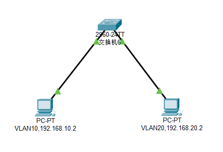
💥正常来说,接入层交换机的上网VLAN是不应该配置IP地址的,IP要从上层路由设备获取。要管理接入层交换机应该用一个单独的VLAN,这里只是为了演示而已
shell
Switch>
Switch>enable
Switch#configure terminal
Enter configuration commands, one per line.  End with CNTL/Z.
Switch(config)#vlan 10                       // 创建vlan 10并进入配置界面
Switch(config-vlan)#name VLAN10              // 设置vlan名称
Switch(config-vlan)#exit
Switch(config)#vlan 20                       // 创建vlan 20
Switch(config-vlan)#name VLAN20
Switch(config-vlan)#exit
Switch(config)#
Switch(config)#interface vlan 10             // 进入vlan 10的配置模式
Switch(config-if)#
%LINK-5-CHANGED: Interface Vlan10, changed state to up
Switch(config-if)#ip address 192.168.10.254 255.255.255.0     // 给vlan 10设置IP地址
// 如果有开启telnet登录功能的话,终端设备还能够通过这个IP地址进行远程登录
Switch(config-if)#exit
Switch(config)#
Switch(config)#interface vlan 20             // 进入vlan 20的配置模式
Switch(config-if)#
%LINK-5-CHANGED: Interface Vlan20, changed state to up
Switch(config-if)#ip address 192.168.20.254 255.255.255.0     // 给vlan 20设置IP地址
Switch(config-if)#exit
Switch(config)#
Switch(config)#interface fastEthernet 0/1           // 进入端口1的配置模式
Switch(config-if)#switchport access vlan 10         // 把端口1划分给vlan 10
Switch(config-if)#
%LINEPROTO-5-UPDOWN: Line protocol on Interface Vlan1, changed state to down
%LINEPROTO-5-UPDOWN: Line protocol on Interface Vlan10, changed state to up
Switch(config-if)#exit
Switch(config)#
Switch(config)#interface fastEthernet 0/2           // 进入端口2的配置模式
Switch(config-if)#switchport access vlan 20         // 把端口2划分给vlan 20
Switch(config-if)#
%LINEPROTO-5-UPDOWN: Line protocol on Interface Vlan1, changed state to down
%LINEPROTO-5-UPDOWN: Line protocol on Interface Vlan20, changed state to up
Switch(config-if)#end
Switch#
%SYS-5-CONFIG_I: Configured from console by console
Switch#
Switch#write                                        // 保存配置
Building configuration...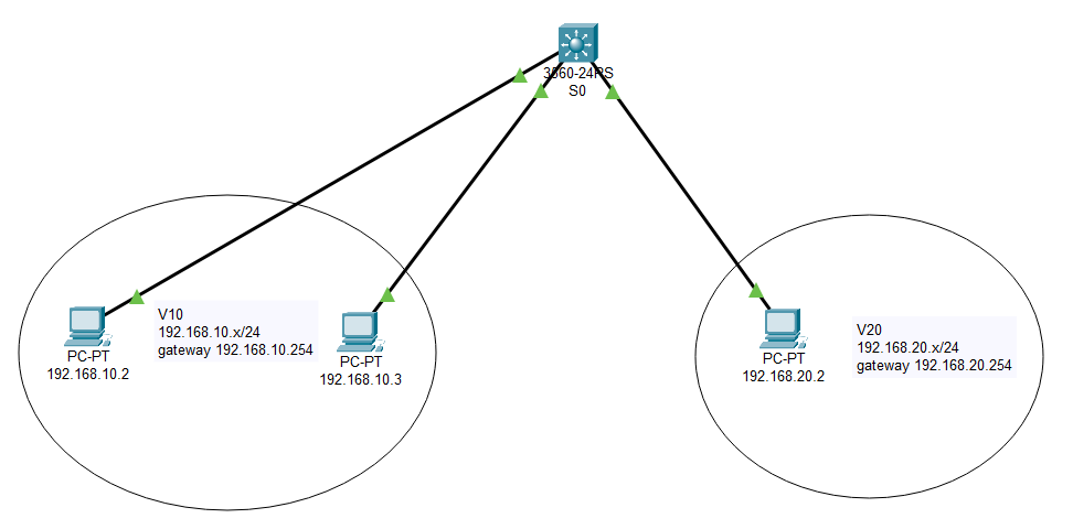
[OK]三层交换机常见组网
方式一
⚡实现方式为创建三层交换机的VLAN间路由
- ①创建VLAN
shell
Switch>
Switch>enable
Switch#vlan database                         // 进入vlan配置界面
% Warning: It is recommended to configure VLAN from config mode,
  as VLAN database mode is being deprecated. Please consult user
  documentation for configuring VTP/VLAN in config mode.
Switch(vlan)#vlan 10 name V10                // 创建vlan 10
VLAN 10 added:
    Name: V10
Switch(vlan)#vlan 20 name V20                // 创建vlan 20
VLAN 20 added:
    Name: V20
Switch(vlan)#exit
APPLY completed.
Exiting....- ②将交换机的端口划分给VLAN
shell
Switch#
Switch#configure terminal
Enter configuration commands, one per line.  End with CNTL/Z.
Switch(config)#interface fastEthernet 0/1          // 进入端口1的配置模式
Switch(config-if)#switchport access vlan 10        // 把端口1划分给vlan 10
Switch(config-if)#exit
Switch(config)#
Switch(config)#interface fastEthernet 0/2          // 进入端口2的配置模式
Switch(config-if)#switchport access vlan 10        // 把端口2划分给vlan 10
Switch(config-if)#exit
Switch(config)#
Switch(config)#interface fastEthernet 0/3          // 进入端口3的配置模式
Switch(config-if)#switchport access vlan 20        // 把端口3划分给vlan 20
Switch(config-if)#exit
Switch(config)#end- ③配置VLAN间的路由
shell
Switch#
Switch#configure terminal
Switch(config)#interface vlan 10                    // 进入vlan 10的配置模式
%LINK-5-CHANGED: Interface Vlan10, changed state to up
%LINEPROTO-5-UPDOWN: Line protocol on Interface Vlan10, changed state to up
Switch(config-if)#ip address 192.168.10.254 255.255.255.0     // 给vlan 10设置IP地址
Switch(config-if)#no shutdown
Switch(config-if)#exit
Switch(config)#interface vlan 20                    // 进入vlan 20的配置模式
%LINK-5-CHANGED: Interface Vlan20, changed state to up
%LINEPROTO-5-UPDOWN: Line protocol on Interface Vlan20, changed state to up
Switch(config-if)#ip address 192.168.20.254 255.255.255.0     // 给vlan 20设置IP地址
Switch(config-if)#no shutdown
Switch(config-if)#exit
Switch(config)#ip routing                    // 开启三层交换机的路由功能
Switch(config)#end
Switch#
Switch#write                                 // 保存配置
Building configuration...
[OK]
Switch#show ip route                         // 查看路由表
Codes: C - connected, S - static, I - IGRP, R - RIP, M - mobile, B - BGP
       D - EIGRP, EX - EIGRP external, O - OSPF, IA - OSPF inter area
       N1 - OSPF NSSA external type 1, N2 - OSPF NSSA external type 2
       E1 - OSPF external type 1, E2 - OSPF external type 2, E - EGP
       i - IS-IS, L1 - IS-IS level-1, L2 - IS-IS level-2, ia - IS-IS inter area
       * - candidate default, U - per-user static route, o - ODR
       P - periodic downloaded static route

Gateway of last resort is not set

C    192.168.10.0/24 is directly connected, Vlan10
C 192.168.20.0/24 is directly connected, Vlan20- ④为终端设备分配IP地址和配置网关
方式二
⚡实现方式为创建三层交换机的VLAN间路由
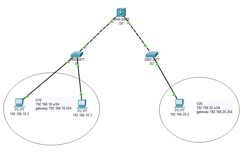
- ①先在二层交换机中创建VLAN,并将上行端口改为trunk模式
shell
Switch>
Switch>enable
Switch#configure terminal
Enter configuration commands, one per line.  End with CNTL/Z.
Switch(config)#vlan 10                                // 创建vlan 10并进入配置界面
Switch(config-vlan)#name V10                          // 设置vlan名称
Switch(config-vlan)#exit
Switch(config)#
Switch(config)#interface fastEthernet 0/1             // 进入端口1的配置模式
Switch(config-if)#switchport access vlan 10           // 把端口1划分给vlan 10
Switch(config-if)#exit
Switch(config)#
Switch(config)#interface fastEthernet 0/2             // 进入端口2的配置模式
Switch(config-if)#switchport access vlan 10           // 把端口2划分给vlan 10
Switch(config-if)#exit
Switch(config)#
Switch(config)#interface fastEthernet 0/24            // 进入端口24的配置模式
Switch(config-if)#switchport mode trunk               // 把端口24强制改为trunk模式
Switch(config-if)#
%LINEPROTO-5-UPDOWN: Line protocol on Interface FastEthernet0/24, changed state to down
%LINEPROTO-5-UPDOWN: Line protocol on Interface FastEthernet0/24, changed state to up
Switch(config-if)#end
Switch#
%SYS-5-CONFIG_I: Configured from console by console
Switch#write                                          // 保存配置
Building configuration...
[OK]- ②接着在三层交换机中创建和二层一样的VLAN
shell
Switch>
Switch>enable
Switch#vlan database                                  // 进入vlan配置界面
% Warning: It is recommended to configure VLAN from config mode,
  as VLAN database mode is being deprecated. Please consult user
  documentation for configuring VTP/VLAN in config mode.
Switch(vlan)#vlan 10 name V10                         // 创建vlan 10
VLAN 10 added:
    Name: V10
Switch(vlan)#vlan 20 name V20                         // 创建vlan 20
VLAN 20 added:
    Name: V20
Switch(vlan)#exit
APPLY completed.
Exiting....
Switch#- ③给三层交换机的VLAN设置IP地址
shell
Switch#
Switch#configure terminal
Enter configuration commands, one per line.  End with CNTL/Z.
Switch(config)#interface vlan 10                       // 进入vlan 10的配置模式
Switch(config-if)#
%LINK-5-CHANGED: Interface Vlan10, changed state to up
%LINEPROTO-5-UPDOWN: Line protocol on Interface Vlan10, changed state to up
Switch(config-if)#ip address 192.168.10.254 255.255.255.0         // 给vlan 10设置IP地址
Switch(config-if)#exit
Switch(config)#
Switch(config)#interface vlan 20                       // 进入vlan 20的配置模式
Switch(config-if)#
%LINK-5-CHANGED: Interface Vlan20, changed state to up
%LINEPROTO-5-UPDOWN: Line protocol on Interface Vlan20, changed state to up
Switch(config-if)#ip address 192.168.20.254 255.255.255.0         // 给vlan 20设置IP地址
Switch(config-if)#exit- ④开启三层交换机的路由功能
shell
Switch(config)#
Switch(config)#ip routing                              // 开启三层交换机的路由功能
Switch(config)#exit
Switch#
%SYS-5-CONFIG_I: Configured from console by console
Switch#write                                           // 保存配置
Building configuration...
[OK]
Switch#
Switch#show ip route                                   // 查看路由表
Codes: C - connected, S - static, I - IGRP, R - RIP, M - mobile, B - BGP
       D - EIGRP, EX - EIGRP external, O - OSPF, IA - OSPF inter area
       N1 - OSPF NSSA external type 1, N2 - OSPF NSSA external type 2
       E1 - OSPF external type 1, E2 - OSPF external type 2, E - EGP
       i - IS-IS, L1 - IS-IS level-1, L2 - IS-IS level-2, ia - IS-IS inter area
       * - candidate default, U - per-user static route, o - ODR
       P - periodic downloaded static route

Gateway of last resort is not set

C    192.168.10.0/24 is directly connected, Vlan10
C 192.168.20.0/24 is directly connected, Vlan20- ⑤为终端设备分配IP地址和配置网关
方式三
⚡实现方式为将三层交换机的交换端口改为路由端口,二层交换机作为接入层交换机保持默认就行
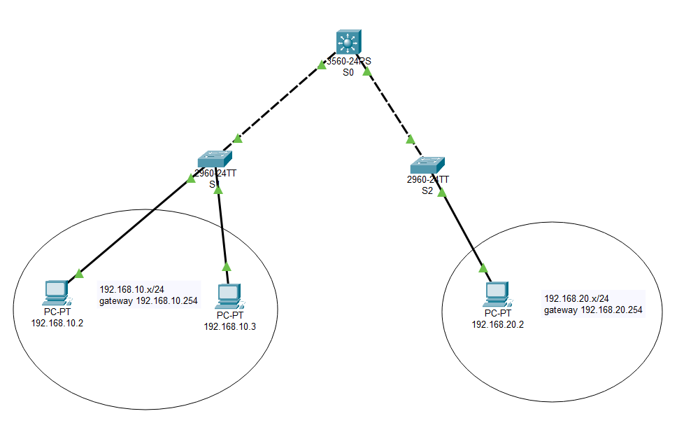
- ①配置三层交换机路由端口
shell
Switch>
Switch>enable
Switch#configure terminal
Enter configuration commands, one per line.  End with CNTL/Z.
Switch(config)#
Switch(config)#interface fastEthernet 0/1           // 进入端口1的配置模式
Switch(config-if)#no switchport                     // 把端口1改为路由端口
Switch(config-if)#
%LINEPROTO-5-UPDOWN: Line protocol on Interface FastEthernet0/1, changed state to down
%LINEPROTO-5-UPDOWN: Line protocol on Interface FastEthernet0/1, changed state to up
Switch(config-if)#ip address 192.168.10.254 255.255.255.0      // 给端口1设置IP地址
Switch(config-if)#no shutdown
Switch(config-if)#exit
Switch(config)#
Switch(config)#interface fastEthernet 0/2           // 进入端口2的配置模式
Switch(config-if)#no switchport                     // 把端口2改为路由端口
Switch(config-if)#
%LINEPROTO-5-UPDOWN: Line protocol on Interface FastEthernet0/2, changed state to down
%LINEPROTO-5-UPDOWN: Line protocol on Interface FastEthernet0/2, changed state to up
Switch(config-if)#ip address 192.168.20.254 255.255.255.0      // 给端口2设置IP地址
Switch(config-if)#no shutdown
Switch(config-if)#exit
Switch(config)#
Switch(config)#ip routing                           // 开启三层交换机的路由功能
Switch(config)#end
Switch#
Switch#write                                        // 保存配置
Building configuration...
[OK]- ②为终端设备分配IP地址和配置网关